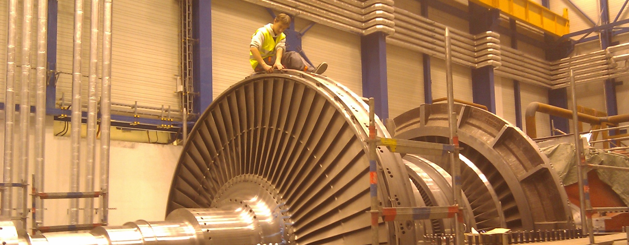
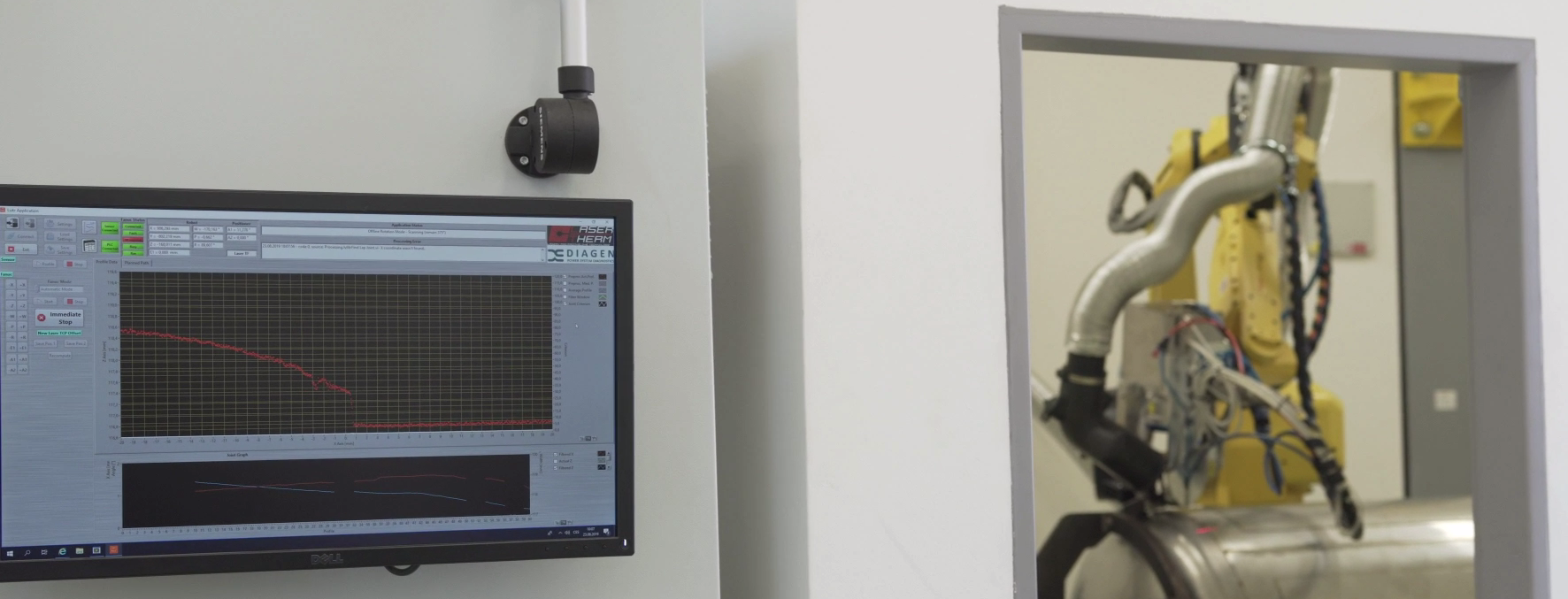
Systems for impact or defect location occur in various real applications such as monitoring systems in power plants, acoustic emission location, location of lightning strikes on aircraft, short-circuit location in electrical grid, leakage detection and location in pipelines and many others. These systems are usually based on the same principle: The impact excites the system and the excited transient wave propagates with a finite velocity into the surrounding. Afterwards, the transient is detected with the sensors and from the detection times the transient origin can be computed.
The method used in DiagEn is designed for use in loose parts monitoring system in nuclear plant primary circuit. In that case, the goal is to find the place where the loose part hit the inner surface. The movement of the loose part is caused by the water circulation inside the primary circuit. An acoustic transient caused by the impact spreads in the steel and is detected on sensors placed in various locations afterwards. The sensors detect the transient in different times because each sensor has different distance of the impact location and the velocity of the transient is finite. The surface of the primary circuit is closed and continuous and we assume that for each possible impact location the transient arrives each point on the surface. The arrival time depends on the distance. After each impact a set of detection times on all sensors is obtained.
The transient trajectory follow the shortest path. (The principle of wave propagation). This is a key fact and we will show why it is important for 3D location method. The geometry of the object as well as the sensor locations are known. The shortest distance from each point on the surface (potential impact location) to each single sensor can be computed. The corresponding times can be computed as well because the velocity is known. This times are the same as times which the transient wave would need to propagate between the origin and the sensors as the transient follows the shortest path. In the first phase of the 3D location method a sufficiently fine grid of points is generated and their shortest distance to each sensor is computed. For each point in the grid the corresponding set of theoretical propagation times to the sensors in stored.
The acoustic transient wave is detected on all of the sensors and a set of detection times is got. After that, the surface grid is browsed and the theoretically computed set of detection times on each point of the grid is compared to the acquired set of detection times. The location on the surface where good agreement between theoretical and acquired times is observed is considered the impact location.
For the comparison, however, a time difference must be used. This is because the absolute propagation times are not available. So the detection times on sensors are pairwise subtracted which results to a set of time differences. The time differences are actually the values assigned to each point in the grid.
Although computing the shortest distances for each point of the grid to the sensors is a computationally expensive operation this does not matter so much as this operation is executed only once. During the execution of the 3D location method only the resulting matrix of time differences for all points and all pairs of sensors.


